Educational / Student Teams
Stress/Strain Design Apparatus
ME 328 · Cal Poly · Team of Three · December 2025
Worked on a three-person team to design and prototype a photoelastic stress/strain apparatus capable of demonstrating axial, bending, and torsional loading for future mechanics of materials laboratories.
Overview
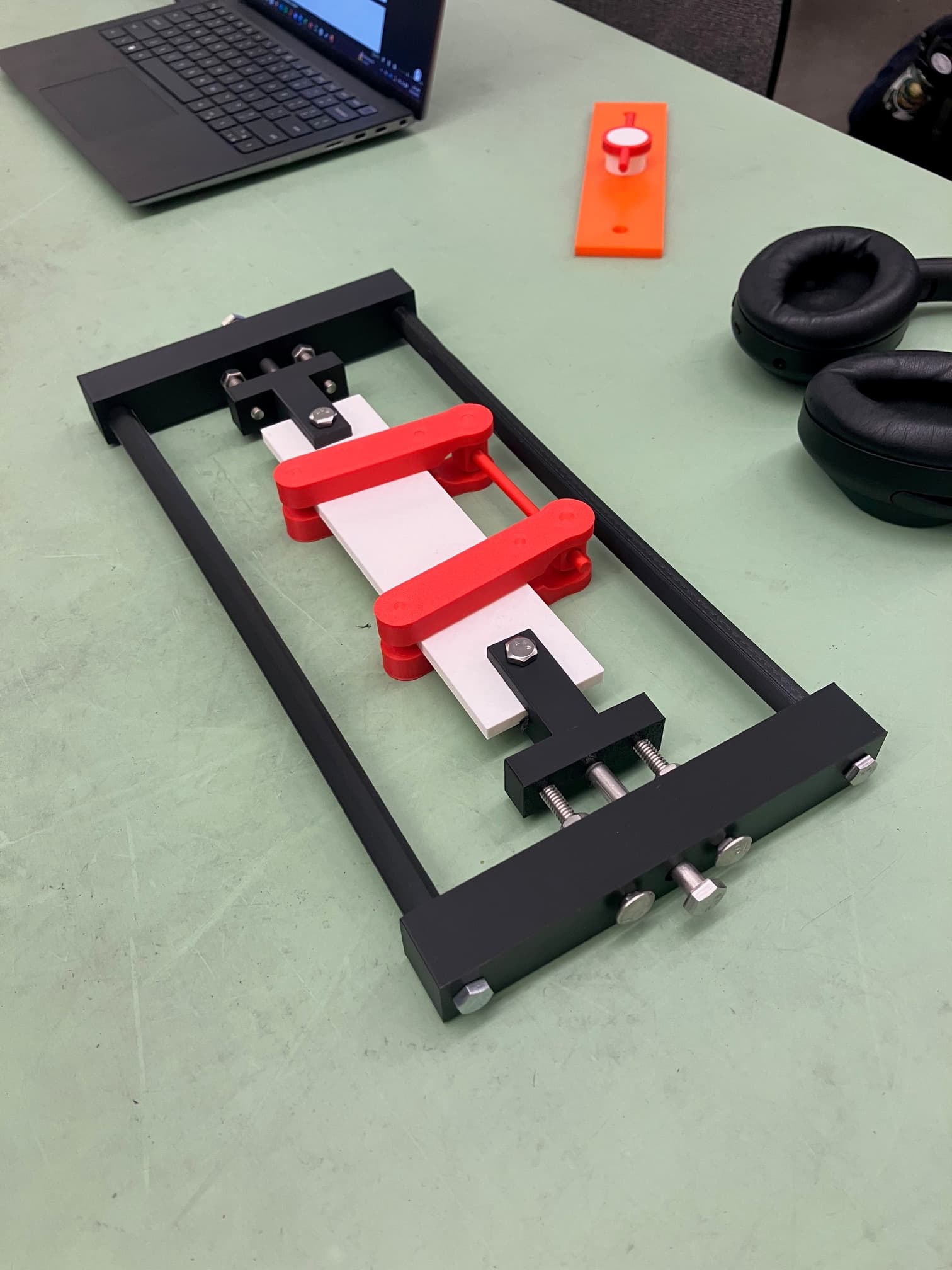
This project focused on designing an educational apparatus capable of visualizing three fundamental loading conditions through photoelasticity. The system was designed to produce a distinct purple stress fringe when viewed through a polariscope, whilst remaining simple to manufacture, assemble, and use in future laboratory courses.
My Role
Designed the four-point bending subsystem, completed the analytical calculations, developed an Excel design tool to iterate through geometric configurations, and validated the design using finite element analysis.
Concept & Design
The apparatus was developed as a teaching tool for future students studying mechanics of materials. Each team member designed one loading configuration, whilst my contribution focused on a four-point bending fixture capable of producing a pure bending moment within the photoelastic specimen.
Analytical Design
Hand calculations were used to determine the geometry and loading required to generate the target purple photoelastic fringe. Because the required stress was relatively low, the design achieved large safety factors whilst producing the desired visual effect.
Pure bending moment
15.6 in-lbf
Maximum analytical bending stress
444.0 psi
Excel Design Tool
To accelerate the design process, I created an Excel tool that evaluated different geometric configurations automatically. This allowed the mechanism to be refined efficiently before completing the detailed finite element analysis.
Finite Element Validation
A mesh-convergence study and finite element analysis were completed to validate the analytical calculations. The simulated bending stress closely matched the theoretical prediction, providing confidence in the final design.
Analytical bending stress
444.0 psi
Simulated bending stress
421.4 psi
Engineering Drawings & Prototype
A full-scale prototype was 3D printed and assembled to demonstrate the three loading configurations during the final class presentation.
Design Results
The completed apparatus achieved the target photoelastic stress level whilst maintaining high structural safety factors. The close agreement between the analytical and simulated stresses supported the validity of the design approach.
Target bending moment
15.6 in-lbf
Lead-screw torque
0.86 in-lbf
ABS safety factor
11.3
6061 aluminum safety factor
90
Reflection
This project strengthened both my structural design skills and my ability to collaborate within a multidisciplinary team. Coordinating three independently designed loading mechanisms required frequent communication to ensure the final apparatus functioned as a cohesive system. Developing the Excel design tool also reinforced the value of automating repetitive engineering calculations to accelerate design iterations.