Educational / Student Teams
Wind Turbine Shroud Baseplate
Cal Poly Wind Power · Blades Subteam · February 2025
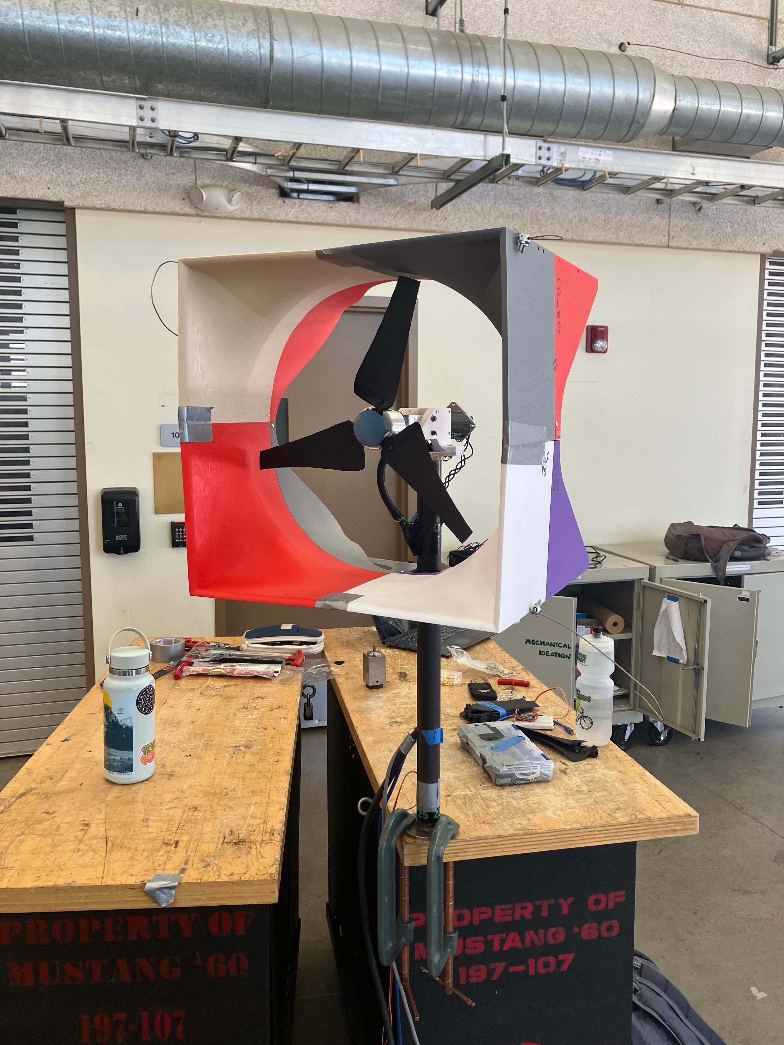
A structural baseplate designed to support an expiremental wind turbine shroud, taking into consideration strength, stiffness, and vibratory requirements.
Overview
Designed and manufactured a structural baseplate for a small-scale wind turbine to support an aerodynamic shroud weighing approximately 10 lbs whilst meeting stiffness, strength, and vibration requirements.
My Role
Developed the baseplate and removable tower-attachment system, completed the analytical stress and deflection calculations, created a semi-automated sizing tool, produced manufacturing drawings, machined the components by hand, and validated the final design using static and vibratory finite element analysis.
Project Overview
The shroud was developed as an experimental aerodynamic concept intended to improve the performance of Cal Poly Wind Power's competition turbine by effectively "catching" the available air from the corners of the square cross section and converging them to the circular sweep of the blades. My responsibility was to design and manufacture the baseplate and attachment hardware whilst satisfying the project's strength, stiffness, and vibration considerations.
Attachment Concept
One of the primary design challenges was developing a secure connection without permanently modifying the turbine tower. Because drilling and welding directly into the tower were prohibited, I developed a removable attachment consisting of a retrofitted pipe clamp and a custom-machined aluminum connector bracket. The assembly transferred the shroud loads into the tower whilst allowing the entire system to be installed and removed without altering the existing tower.
Hand Calculations
I first completed hand calculations with an arbitrary material and thickness to estimate the combined stresses and maximum deflection produced by a worst-case-scenario loading event. These calculations established the relationships between the applied loading, material properties, baseplate geometry, required thickness, and factor of safety. Later iteration with the Excel tool allowed for the finalized values to be obtained.
Maximum combined stress
41.2 MPa
Maximum deflection
3.0 mm
Factor of safety
6.7
Semi-Automated Design Tool
To accelerate material and geometry selection, I developed a parameter-driven Excel tool to evaluated specified materials and geometric configurations automatically. The tool determined the minimum plate thickness required to exceed a specified factor of safety whilst simultaneously checking the design against the allowable deflection limit. This allowed the team to compare suitable options with the scrap material available in the shop and ultimately reuse aluminum flat plate from another project, reducing both cost and material waste.
Finite Element Analysis
After finalizing the design, I completed a mesh-convergence study to identify an element size that produced stable results whilst minimizing computational complexity. A static finite element analysis was used to validate the analytical calculations from the design tool for stress and deflection. In the simulation, geometric constraints and boundary conditions produced a localized stress concentration near the constrained mounting hole, so the probe tool was used within the area of concern to determine the proper maximum stress.
Combined stress (analytical)
41.2 MPa
Combined stress (simulated)
42.6 MPa
Deflection (analytical)
3.0 mm
Deflection (simulated)
5.0 mm
Factor of safety
6.7
Vibratory Analysis
I also simulated a modal analysis to verify that the structure would not resonate under the turbine's normal operating conditions. With a worst-case loading configuration, the simulated first natural frequency was 75.7 Hz, remaining well above the blades' maximum operating frequency of 38.3 Hz. This separation provided confidence that the baseplate and shroud assembly would not experience resonant interactions during normal operation.
First natural frequency
75.7 Hz
Maximum blade frequency
38.3 Hz
Manufacturing
Following completion of the analytical and computational design, I produced manufacturing drawings for both the structural baseplate and custom attachment bracket. The components were then fabricated using the waterjet for the baseplate and manual mill for the connector bracket, before assembly with the selected hardware, and integration into the turbine before physical testing.
Physical Testing
The completed assembly was installed on the turbine and structurally evaluated downwind with a large ducted fan. The baseplate successfully supported the shroud with minimal visible movement at the shroud throat, confirming that the structural attachment performed as intended. As later testing in the wind tunnel confirmed, the gains in power output were not sufficient to justify incorporating the concept into the final competition turbine.
Design Results
The final design satisfied the project's structural, stiffness, attachment, and vibration requirements whilst avoiding permanent modification to the turbine tower. The analytical and simulated stress results showed close agreement, and the modal analysis confirmed that the first natural frequency remained safely above the maximum blade frequency. Physical testing further demonstrated that the removable attachment provided sufficient rigidity during operation.
Supported shroud weight
~10 lb
Factor of safety
6.7
Combined stress (analytical)
41.2 MPa
Combined stress (simulated)
42.6 MPa
Deflection (analytical)
3.0 mm
Deflection (simulated)
5.0 mm
Maximum blade frequency
38.3 Hz
First natural frequency
75.7 Hz
Reflection
Although the shroud concept wasn't ultimately incorporated into the final turbine because its aerodynamic properties, the baseplate successfully met its structural and functional requirements. The project reinforced the importance of evaluating an engineering concept as a complete system, since partial success does not necessarily make the broader concept worthwhile. It also gave me valuable experience contributing an independently designed subsystem to a large multidisciplinary engineering team working toward a shared competition goal. Cal Poly Wind Power went on to place 1st overall in the DOE Collegiate Wind Competition and 2nd in Turbine Design.