Personal
Compressed Air Engine
Personal Project · June 2024-August 2025
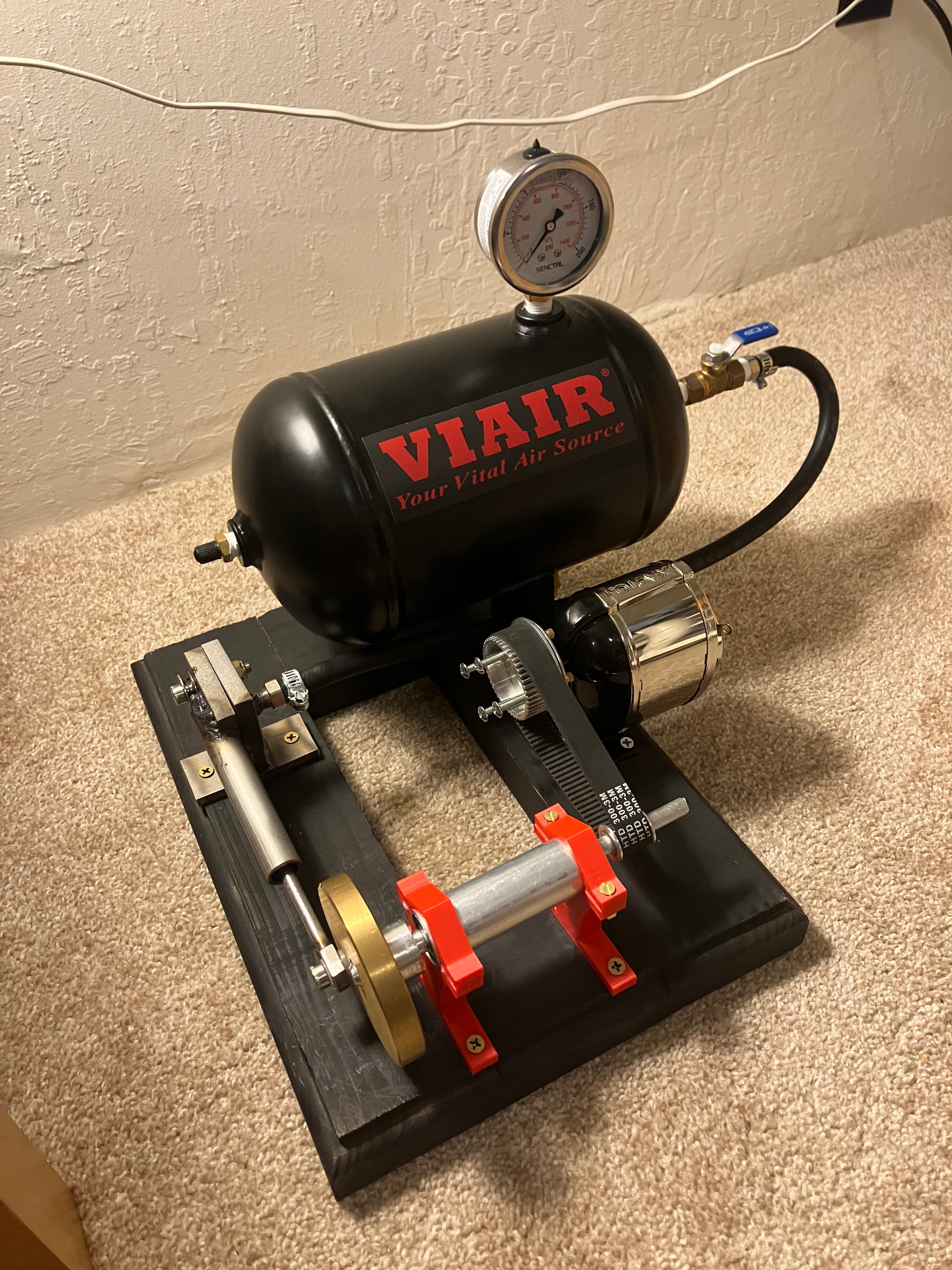
A compressed-air engine designed and manufactured with custom components, then retrofitted with belts and pulleys to power a pencil sharpener.
Overview
Designed and manufactured a compressed-air engine containing 12 custom parts designed and machined from scratch. After completing the engine, I added a 3:1 belt reduction to increase its output torque and operate a pencil sharpener.
My Role
Developed the mechanical concept, modeled the engine and its components in SolidWorks, produced the manufacturing drawings, machined and fabricated 12 custom parts, assembled and tested the complete system, and designed the belt-drive retrofit.
Project Overview
This project began as an open-ended attempt to design and manufacture a functioning compressed-air engine from the ground up. Starting with a general idea of the desired layout, I developed several revisions in SolidWorks to establish the geometry, component interfaces, and motion before entering the machine shop. The final assembly contains more than 30 parts and converts compressed-air into reciprocating piston motion and continuous rotation for a flywheel and driveshaft.
Manufacturing & Assembly
Manufacturing the engine required several months of intermittent work and incorporated nearly every process available to me in the machine shop. I designed and manufactured 12 custom components using milling, turning, 3D printing, welding, sawing, grinding, and even woodworking before fitting them into the complete assembly. Producing each component individually made careful dimensional planning essential, since small inaccuracies could accumulate across the crankshaft, piston, connecting rod, bearings, and supporting structure.
Testing & Design Limitation
The completed engine successfully operates at a supply pressure of 100 psi and reaches speeds in excess of 800 rpm. Its primary limitation resulted from the manufacturing sequence used for the cylinder-head interface. I fly-cut the sealing surface before welding the surrounding assembly, and the heat introduced during welding distorted the previously machined face. The resulting air leakage is significant, and it shortens the engine's runtime considerably. This demonstrated the importance of completing distortion-producing operations before final machining of critical surfaces.
Maximum measured speed
802 rpm
Operating pressure
100 psi
Moving components
6
Pencil-Sharpener Retrofit
After the engine was operating successfully, I retrofitted it with a belt-and-pulley system to power a pencil sharpener. The 3:1 reduction decreases the output speed whilst increasing the available torque, allowing the engine to overcome the sharpener's resistance. Although pressurizing the air reservoir requires far more energy than sharpening a pencil manually, the retrofit provides a fun demonstration of power transmission and mechanical advantage.
Pulley reduction ratio
3:1
Custom parts manufactured
12
Total assembly parts
30+
Manufacturing Drawings
Before entering the machine shop, I produced detailed drawings for the custom components to define their dimensions, tolerances, and interfaces. These drawings guided the manufacturing process and helped ensure that the independently produced parts would align and move properly when brought together in the final assembly. These were some of the first engineering drawings I ever made, and it's interesting to look back years later and see how far I've come since then!
Design Results
The completed engine successfully converted compressed air into continuous rotary motion and reached speeds above 800 rpm. Its six moving components operated together within an assembly of more than 30 total parts, including 12 components that I designed and manufactured. The later belt-drive retrofit also provided sufficient torque to operate a pencil sharpener.
Maximum measured speed
800+ rpm
Operating pressure
100 psi
Pulley reduction ratio
3:1
Custom parts manufactured
12
Moving components
6
Total assembly parts
30+
Reflection & Next Steps
This project tested nearly every manufacturing process I knew how to perform at the time, and reinforced the importance of designing around the complete manufacturing sequence. Remachining the warped cylinder interface would reduce air leakage and substantially improve the engine's runtime. Despite that limitation, seeing a collection of individually manufactured components operate as a complete engine—and eventually sharpen a pencil—made the extended build process worthwhile.